Monday, March 30, 2009

IPv6 Tunneling


I was practicing IPv6 in home by using Cisco 7200 series router so I think of a lab that if we have IPv6 enabled router on both side and I want to communicate them by using IPv4 cloud so what will be the procedure for it, so after studying books (Data Communication by Behrouz A. Forouzan and TCP/IP Routing by Jeff Doyle), I found that one of the method used for it is tunneling. The tunnel can be of four type’s i.e.
 Router to Router
 Host to Router
 Host to Host
 Router to Host
My Lab is between Router to Router. A tunnel is configured between Cisco routers by creating tunnel interface in the routers that border the IPv6 and IPv4 networks. IPv6 subnets are defined on both side and IPv6 dynamic protocol is in used RIPng, BGP or OSPFv3, in our lab we used RIPng. A tunnel is configured between these two IPv6 enable routers to communicate through IPv4 cloud.
I took just two 7200 series router and performed this lab. So here are the steps and configuration of the Lab.

Router_A (config) # ipv6 unicast-routing

Router_A (config) # interface serial 1/0
Router_A (config) # ip address 1.1.1.1
Router_A (config) # no shutdown
Router_A (config) # keepalive
Router_A (config) # clock rate 64000

Router_A (config) # interface FastEthernet 0/0
Router_A (config) # ipv6 enable
Router_A (config) # ipv6 address 2001:0:0:1:: 1/64
Router_A (config) # ipv6 rip 1 enable


Now to define Tunnel Interface on Router_A

Router_A (config) # interface Tunnel 0
Router_A (config) # ipv6 address 2001:0:0:5:: 1/64
Router_A (config) # tunnel source serial 1/0
Router_A (config) # tunnel destination 1.1.1.2
Router_A (config) # tunnel mode ipv6ip
Router_A (config) # ipv6 rip 1 enable


Now the configurations on the other side are as under

Router_B (config) # ipv6 unicast-routing

Router_B (config) # interface serial 1/0
Router_B (config) # ip address 1.1.1.2
Router_B (config) # no shutdown
Router_B (config) # keepalive

Router_B (config) # interface FastEthernet 0/0
Router_B (config) # ipv6 enable
Router_B (config) # ipv6 address 2001:0:0:3:: 1/64
Router_B (config) # ipv6 rip 1 enable


Now to define Tunnel Interface on Router_B

Router_B (config) # interface Tunnel 0
Router_B (config) # ipv6 address 2001:0:0:5:: 2/64
Router_B (config) # tunnel source serial 1/0
Router_B (config) # tunnel destination 1.1.1.1
Router_B (config) # tunnel mode ipv6ip
Router_B (config) # ipv6 rip 1 enable


Now to check the communication that whether the two router are communicating with each other using IPv4 cloud or not, we can check this by Ping or Traceroute


Router_A# Ping ipv6 2001:0:0:3:: 1
OUTPUT:

Types escape sequence to abort.
Sending 5, 100-byte ICMP echos to 2001:0:0:3:: 1, timeout in 2 seconds:
!!!!!
Success rate is 100 percent <5/5>, round-trip min/avg/max = 12/58/188 ms


Router_A# Traceroute
OUTPUT:

Types escape sequence to abort.

Tracing the route to 2001:0:0:3:: 1

1 2001:0:0:3:: 1 56 msec 48 msec 72 msec


The detail output can also be seen from the figure attached.

Hope it will be informative for you.
Monday, March 2, 2009

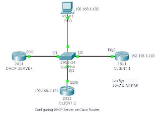
Configuring Cisco Router as a DHCP Server


Thank GOD, atlast i have done it.....lolz. I was trying from last couple of days to configure cisco router as a DHCP server but there were some problems but anyway today i have done with that. Here is the step wise configuration of the Lab, may be it will help someone. so here we go!

Note: connect the devices as shown in the figure

The configuration on cisco router to be DHCP server as follow:

SERVER(config)# interface fasethernet 0/0
SERVER(config-if)# ip address 192.168.1.1 255.255.255.0
SERVER(config-if)# no shutdown
SERVER(config-if)# exit

SERVER(config)# ip dhcp excluded-address 192.168.1.1 192.168.1.99
SERVER(config)# ip dhcp pool mypool
SERVER(config)# network 192.168.1.0 255.255.255.0
SERVER(config)# default-router 192.168.1.1
SERVER(config)# dns-server 192.168.1.1


Now the configuration on the client side is just simple

CLIENT_1(config)# do show ip interface brief
CLIENT_1(config)#interface fastethernet 0/0
CLIENT_1(config-if)# ip address dhcp
CLIENT_1(config-if)# no shutdown


Now wait for the log message on console, if not seen don't worry after a while CLIENT_1 should obtained ip from DHCP Server.

CLIENT_1# show ip interface brief
CLIENT_1# ping 192.168.1.1


You can check the DHCP bindings by a command

CLIENT_1# show ip dhcp bindings

The output of my lab for this bindings command is as follow:
IP address Client-ID/ Lease expiration Type
Hardware address
192.168.1.100 0001.4303.C501 -- Automatic
192.168.1.101 0004.9A66.B101 -- Automatic
192.168.1.102 000A.41D2.1543 -- Automatic


The same commands are on CLIENT_2 as we did on CLIENT_1. For pc just check the option (ip configuration......DHCP).

Enjoy it!

Sunday, March 1, 2009

Configuring Router to run SDM

Cisco Router and Security Device Manager (SDM) is an graphical, Web-based device management tool supported on Cisco 830 series through Cisco 7301 routers. SDM provides smart wizards and advanced configuration support for LAN and WAN configurations, NAT, Firewall Policy, Intrusion Prevention (IPS), IPSec virtual private network (VPN), Easy VPN Client and Server configurations, Digital Certificates, and Quality of Service (QoS) Policy features.

You can download SDM free of cost from Cisco site.
www.cisco.com/go/sdm

Follow the steps below to configure a router to run SDM.

Step 1:
Connect to your router using Telnet, SSH or via console.
Enter the global configuration mode using the command:

Router>enable

Router#conf terminal

Router(config)#


Step 2 :
Enable the router's HTTP/HTTPS server, using the following Cisco IOS commands:

Router(config)# ip http server

Router(config)# ip http secure-server

Router(config)# ip http authentication local


Note:- HTTPS is enabled only for crypto enabled IOS images.

Step 3:

Create a user with privilege level 15.

Router(config)# username cisco privilege 15 password 0 cisco

Note:- Replace cisco and cisco with the username and password that you want to configure.

Step 4:

Configure SSH and Telnet for local login and privilege level 15:

Router(config)# line vty 0 4

Router(config-line)# privilege level 15

Router(config-line)# login local

Router(config-line)# transport input telnet

Router(config-line)# transport input telnet ssh


Router(config-line)# exit

Step 5:
(Optional) Enable local logging to support the log monitoring function:

Router(config)# logging buffered 51200 warning